Chapter 2 - Your BOE Shield-Bot's Servo Motors
In this chapter, we begin building and testing circuits with Parallax continuous rotation servos, resistors, and LED lights. Along the way, you’ll start learning the basics of building circuits and making the Arduino interact with them. By the end of the chapter, you’ll have a pair of servos connected, each with its own signal indicator light, and you’ll be writing sketches to control servo speed and direction.
Objectives/Outcomes:
By the time you complete this section you will be able to: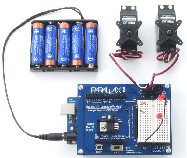
- Connect, adjust, and test the Parallax Continuous Rotation Servo motors
- Calibrate the Continuous Rotation Servo motors
- Demonstrate ability to read a wiring diagram
- Know the difference between a wiring diagram and a schematic
- Construct a circuit with LEDs and Resistors
- Know how long a millisecond lasts and how to abbreviate it
- Understand how the speed and direction are controlled for the Continuous Rotation Servo motors
- Understand Pulse Width Modulation and how it is used with the Servos
- Understand how to send and receive information from the Ports on the board
- Write code to send commands to turn LEDs on and off
- Write code to control the servo direction and speed
- Include libraries as part of code
Assignments:
- View the videos and documents in the Overview section of this lesson.
- Open the worksheet document and review the questions.
- Read and follow the instructions in Robotics with the BOE Shield-Bot for Arduino Chapter 2.
- Download Chapter 2 Arduino code
- Complete the BOE Shield-Bot Activities assigned by your instructor, following the step-by-step tutorials and videos in the Activities section below. If self-study, do all the "Your Turn" parts for each activity in the chapter. (Note: It is only by typing in the commands that you truly begin to understand programming. So don't short change yourself.)
- Review the Key Points or FAQs below.
- Answer the questions in the worksheet document.
- Complete the Programming Exercises at the end of the chapter and fill out the worksheet for them.
- Complete the Projects at the end of the chapter and fill out the worksheet for them.
- Check your answers. When complete, turn in the Worksheet Doc to your instructor (print, email or other method defined by your instructor). Self-study students can optionally send to a parent, mentor or friend.
Overview
Activity 1: Board of Education Shield Setup
Tutorial - Step by Step Instructions
Activity 2: Build and Test LED Indicator Lights
Tutorial - Step by Step Instructions
Activity 3: LED Servo Signal Monitors
Tutorial - Step by Step Instructions
Activity 4: Connect Servo Motors and Batteries
Tutorial - Step by Step Instructions
Activity 5: Centering the Servos
Tutorial - Step by Step Instructions
Activity 6: Testing the Servos
Tutorial - Step by Step Instructions
Additional Resources
Arduino Coding Reference (Help for Arduino Code)
Key Points or FAQs
What is a resistor and how can you tell the difference between the different values?
A resistor is an electronic component used to limit the current in a circuit, they are manufactured to provide a precise quantity of electrical resistance. The resistance is measured in Ohms. You can identify the resistor and its quantity of electrical resistance by reading the colored bands on it. Each band color equates to a number (see chart). This means that each combination of bands represents a different value. See video: Resistor Identification (4 min) Here is another introduction to Resistors that demonstrates how you can make your own resistor and how to test a resistor with a meter (6:23).
To distinguish left from right there is a gap between the 3rd and 4th bands.
- band 1 is the first digit of the component value (left side)
- band 2 is the second digit of the component value
- band 3 is the decimal multiplier (number of zeroes)
- band 4 if present, indicates tolerance of value in percent (no band means 20%)
See this resistor identification chart. and this Wikipedia Article on Electronic Color Codes
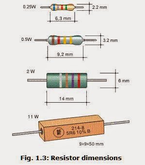
Most resistors used in electronics are small, like the ones we will use with our circuits. But larger ones are available for other uses. Most resistors found in small electronic devices such as portable radios are rated at 1/4 (0.25) watt or less. The power rating of any resistor changes with its physical size, the larger the size, the higher the watts. See how the physical size of the resistor (mm) changes its wattage rating, measured in watts (W) in the picture below. Because resistors dissipate heat energy as the electric currents through them overcome the “friction” of their resistance, resistors are also rated in terms of how much heat energy they can dissipate without overheating and sustaining damage. Learn more about resistors in this All About Circuits Electronics Textbook.
What does a cathode and an anode relate to and how do you identify them?
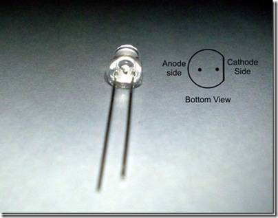
The Cathode and Anode are part of an LED. The Cathode side is the side of the leads that is shorter. Also, the LED is flat on the cathode side. The anode side of the LED is longer and is rounded on the LED. A diode is a one-way electric current valve, and a light-emitting diode (LED) emits light when current passes through it. The cathode and anode sides help you to place the LED into the circuit in the correct direction so that the current passes through it. Read more about LEDs: https://www.kpsec.freeuk.com/voltage.htm
These terms are also used in other electrical devices. The cathode is the negatively charged electrode. The cathode attracts cations or positive charge. The cathode is the source of electrons or an electron donor. It may accept positive charge.
The anode is the positively charged electrode. The anode attracts electrons or anions. The anode may be a source of positive charge or an electron acceptor. (One way to remember these is like grades: A plus and C minus)
What is the difference between a schematic drawing and a wiring or circuit diagram?
A wiring or circuit diagram uses illustrations to closely match what the components look like in real life to demonstrate how a circuit is assembled. A schematic uses known symbols that represent electrical components to illustrate the construction of a circuit.
Find out more about reading a circuit diagram: https://www.epemag.net/how-to-read-circuit-diagrams.html
Another step by step on how to read a circuit diagram: https://www.instructables.com/id/HOW-TO-READ-CIRCUIT-DIAGRAMS/
How to read schematics (with an interactive quiz): https://www.learn-c.com/schemat.htm
Another link for reading schematics with some of the most common symbols: https://artsites.ucsc.edu/EMS/music/tech_background/schematics/ReadSchem.html
Describe Voltage and Current and how the two relate to each other.
Voltage is potential energy that can be used within a circuit measured in Volts. Current is how much voltage is carried throughout the system measured in amps.
Volts is abbreviated V. When you apply voltage to a circuit, it’s like applying electrical pressure. By convention, 5 V means “5 V higher than ground.” Ground is considered 0 V.
Ground is abbreviated GND. The term ground originated with electrical systems where this connection is actually a metal rod that has been driven into the ground. In portable electronic devices, ground is commonly used to refer to connections that go to the battery supply’s negative terminal.
Current refers to the rate at which electrons pass through a circuit. You will often see measurements of current expressed in amps, which is abbreviated A. The currents you will use here are measured in thousandths of an amp, or milliamps. For example, 10.3 mA of current passes through the circuit.
Find out more about Amps, Watts, Volts, and Ohms
Learn more about difference between voltage and current with Sparkfun Videos: What is Voltage and What is Current and Ohms Law
and read this https://electronicsclub.info/voltage.htm
What is Pulse Width Modulation (PWM)?
Adjusting the property of a signal to carry information is called modulation. Servo control signals are a series of high pulses separated by low resting states. How long the high pulse lasts—how wide the high pulse looks in a timing diagram—determines the speed and direction that the servo turns. That adjustable pulse width carries the servo setting information. Therefore, we can say that servos are controlled with pulse width modulation, abbreviated PWM.
Learn more about Pulse Width Modulation with this Sparkfun Video and Learn How PWM is used in many devices (Note: it has a commerical starting at 4:00)
What are the benefits of a Loop?
The Loop function allows you to repeat a set of code commands over and over. Here is an example loop which blinks an LED on and off. All the commands to run within the loop are placed between the curly braces.
void loop() // Main loop auto-repeats
{
digitalWrite(13, HIGH); // Pin 13 = 5 V when set to HIGH, LED emits light
delay(500); // wait for 0.5 seconds
digitalWrite(13, LOW); // Pin 13 = 0 V when set to LOW, LED no light
delay(500); // wait for 0.5 seconds
}
What is RPM?
Revolutions Per Minute—the number of full rotations the servo turned in one minute.
It is a measure of speed, similar to a vehicle's speed is measured in MPH - miles per hour.
What is a Millisecond?
• A millisecond is a one-thousandth of a second, abbreviated ms. (5,000 ms = 5 seconds)
• A microsecond is a one-millionth of a second, abbreviated μs. (5,000,000 μs = 5 seconds)
• There are 1000 microseconds (μs) in 1 millisecond (ms). (5,000 μs = 5 ms = .005 seconds)
• There are 1,000,000 microseconds (μs) in 1 second (s).
What is the formula for determining how long a servo will run in pulses? (IS THIS STILL VALID FOR BOE-SHIELD?)
Number of pulses = Time s / 0.0246 s = Time / 0.0246
For example if you want a servo to run for 3 seconds:
Number of pulses = 3 / 0.0246 = 122
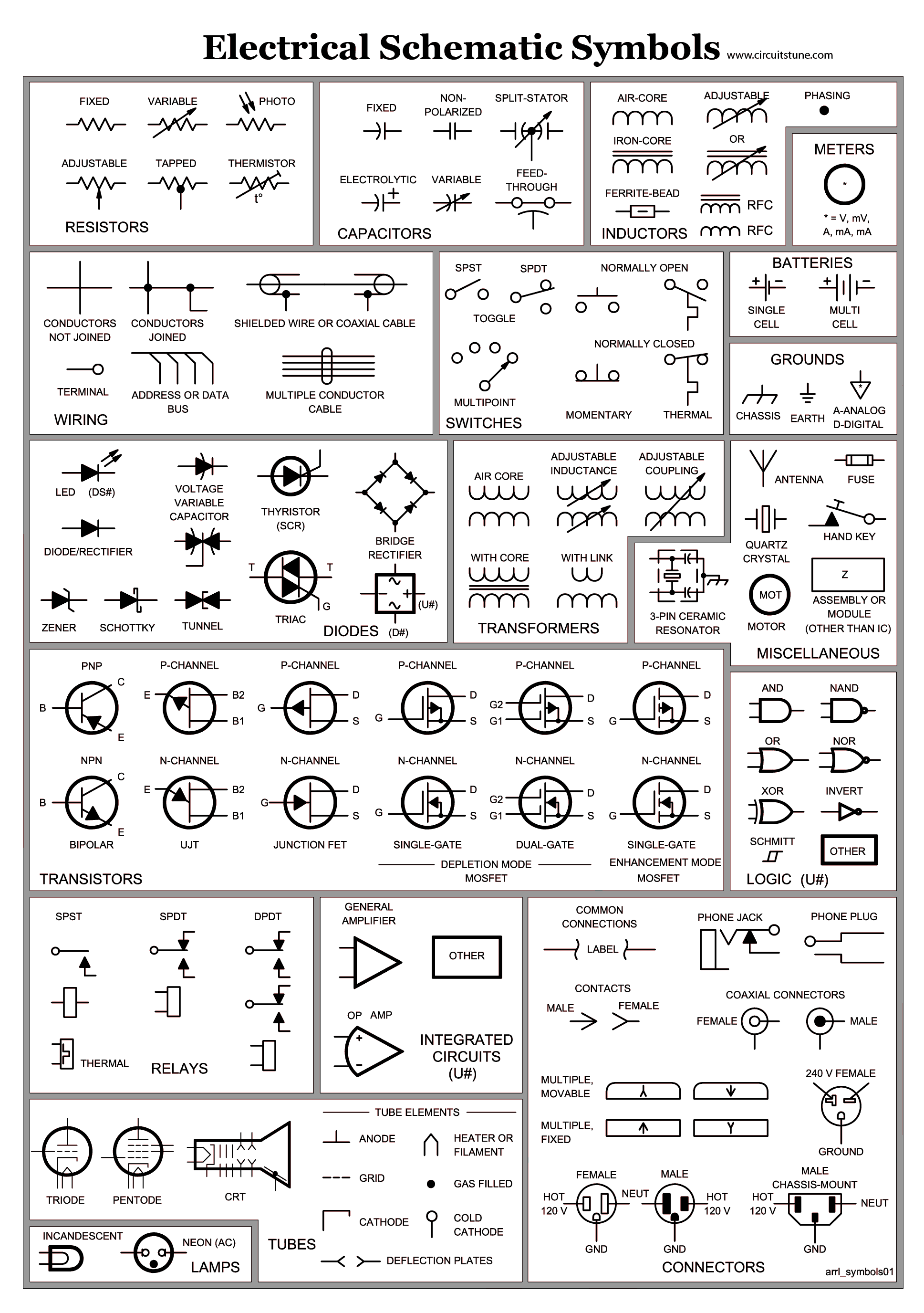
What are some of the most common symbols found on Schematic Diagrams?
OLD Videos (These are currently Boe-Bot NOT Boe Shield)