Chapter 2 - Your Boe-Bot's Servo Motors
In this chapter, we begin building and testing circuits with Parallax continuous rotation servos, resistors, and LED lights. Along the way, you’ll start learning the basics of building circuits and making the Basic Stamp interact with them. By the end of the chapter, you’ll have a pair of servos connected, each with its own signal indicator light, and you’ll be writing programs to control servo speed and direction.Objectives/Outcomes:
By the time you complete this section you will be able to:
- Connect, adjust, and test the Parallax Continuous Rotation Servo motors
- Understand how variables are used in the Basic Stamp language and the size of variables that can be stored
- Understand and use the PAUSE command
- Understand and use the DO...LOOP command
- Understand and use the FOR...NEXT command
- Understand and use the HIGH and LOW commands as a way of making the BASIC Stamp connect an I/O pin to Vdd or Vss
- Construct an LED circuit to test the commands
- Understand and use the PULSOUT command
- Know how long a millisecond lasts and how to abbreviate it
- Understand how the speed and direction are controlled for the Continuous Rotation Servo motors
- Calibrate the Continuous Rotation Servo motors
- Know the difference between a wiring diagram and a schematic
- Demonstrate ability to read a wiring diagram
Assignments:
- View the videos and documents in the Overview section of this lesson.
- Open the worksheet document and review the questions.
- Read and follow the instructions in Robotics with the Boe-Bot Chapter 2.
- Download Chapter 2 Basic code.
- Complete the Boe-Bot Activities assigned by your instructor, following the step-by-step tutorials and videos in the Activities section below. If self-study, do all the "Your Turn" parts for each activity in the chapter. (Note: It is only by typing in the commands that you truly begin to understand programming. So don't short change yourself.)
- Review the Key Points or FAQs below.
- Answer the questions in the worksheet document.
- Complete the Programming Exercises at the end of the chapter and fill out the worksheet for them.
- Complete the Projects at the end of the chapter and fill out the worksheet for them.
- Check your answers. When complete, turn in the Worksheet Doc to your instructor (print, email or other method defined by your instructor). Self-study students can optionally send to a parent, mentor or friend.
Overview
Activity / Process
Key Points or FAQs:
What does a Do Loop do in a program?
The Do Loop command repeats all of the lines of code contained within it. Often there are conditions used to tell the loop when to stop. For example:
DO WHILE x < 1
(enter code commands here)
LOOP
This Do Loop command will keep repeating the code commands before the LOOP until the value of the variable x is less than 1. Note: One of the commands within this LOOP must decrease the value of the variable x, or the loop will run forever.
What is a resistor and how can you tell the difference between the different values?
A resistor is an electronic component used to limit the current in a circuit. You can tell the difference between the values by reading the colored stripes on them. Each stripe combination represents a different value. See video: Resistor Identification (4 min)
What does a cathode and an anode relate to and how do you identify them?
The Cathode and Anode are part of an LED. The Cathode side is the side of the leads that is shorter. Also, the LED is flat on the cathode side. The anode side of the LED is longer and is rounded on the LED.
Read more about LEDs: https://www.kpsec.freeuk.com/voltage.htm
photo
What is the difference between a schematic drawing and a wiring or circuit diagram?
A wiring or circuit diagram uses illustrations to closely match what the components look like in real life to demonstrate how a circuit is assembled. A schematic uses known symbols that represent electrical components to illustrate the construction of a circuit.
Find out more about reading a circuit diagram: https://www.epemag.net/how-to-read-circuit-diagrams.html
Another step by step on how to read a circuit diagram: https://www.instructables.com/id/HOW-TO-READ-CIRCUIT-DIAGRAMS/
How to read schematics (with an interactive quiz):
https://www.learn-c.com/schemat.htm
Another link for reading schematics with some of the most common symbols: https://artsites.ucsc.edu/EMS/music/tech_background/schematics/ReadSchem.html
Describe Voltage and Current and how the two relate to each other.
Voltage is potential energy that can be used within a circuit measured in Volts. Current is how much voltage is carried throughout the system measured in amps.
Find out more about Amps, Watts, Volts, and Ohms:
https://science.howstuffworks.com/environmental/energy/question501.htm
Another source for learning about difference between voltage and current for electronics: https://www.kpsec.freeuk.com/voltage.htm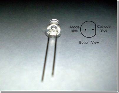
What does the Pulsout command do?
The Pulsout command sends signals to the servos for a controlled amount of duration. This allows the servos to move based on a number of pulses and makes movement exact and repeatable.
How does the debug command work and why do you need it?
The debug command works by entering the Debug keyword and any variable or value after it. The results of the variables or values are displayed in the debug window.
For Example: DEBUG X + 8
This will display in the debug window the result of the current value of the variable added to 8. This is useful when the value of the variable X is being modified and you need to know its current value.
What are the benefits of a For Loop?
The For Loop allows you to repeat set of code commands a specified number of times.
For example:
FOR I = 1 to 20
(enter code commands here)
NEXT
This example For Loop will repeat the code commands 20 times.
What is the formula for determining how long a servo will run in pulses?
Number of pulses = Time s / 0.0246 s = Time / 0.0246
For example if you want a servo to run for 3 seconds:
Number of pulses = 3 / 0.0246 = 122